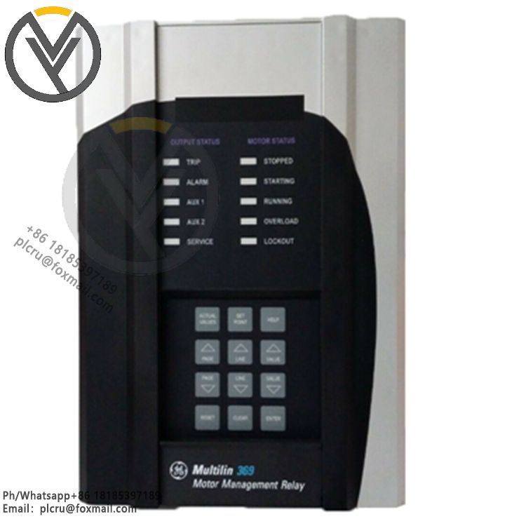
369-HI-R-M-0-E-O-E GE Multilin 369 Motor Management Relay
Delivery time 3 days
Product origin New/used
Email plcru@foxmail.com
Mobile/wechat /WhatsApp +86 18185397189
GE Multilin 369-HI-R-M-0-E-O-E Three-Phase Motor Integrated Management and Prote
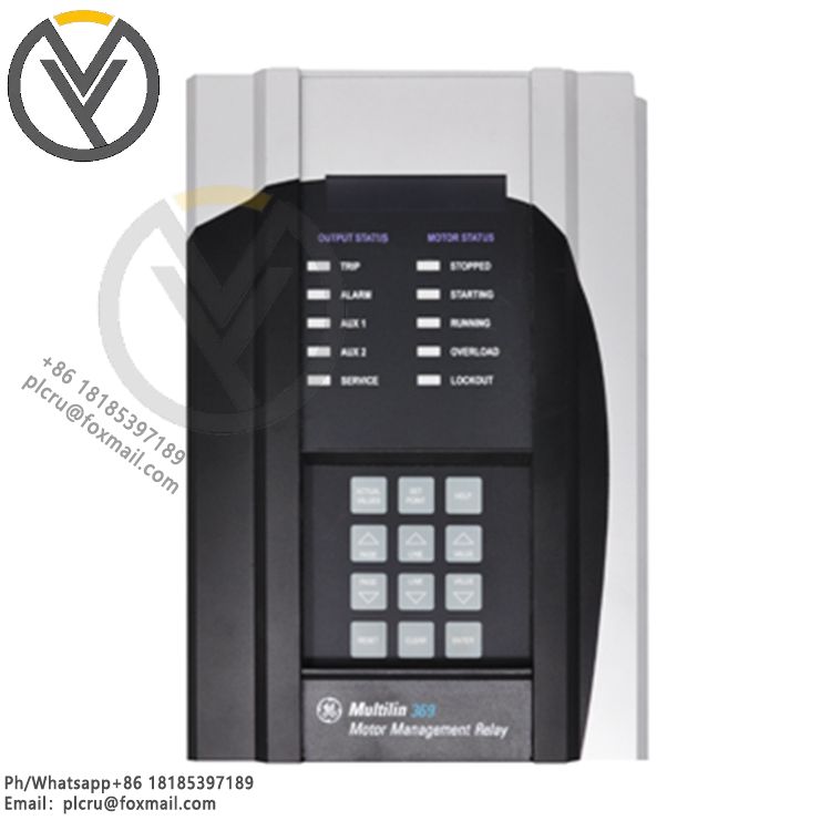
GE Multilin 369-HI-R-M-0-E-O-E Three-Phase Motor Integrated Management and Protection Relay
This product belongs to the GE Vernova Multilin 369 series and is specifically designed for comprehensive protection, measurement and control, and start/stop logic management of medium and low voltage three-phase asynchronous motors. It is widely used in high-power, high-voltage/low-voltage motor circuits in petrochemical, power plant, mining, and water treatment plants.
I. Model Segment Explanation
369: Basic model of the 369 series;
HI: Wide voltage operating power supply, 50~300VDC / 60~265VAC, total power consumption 20VA (peak 65VA), built-in 3.15A fuse;
R: Built-in 12-channel three-wire RTD temperature measurement channel, supporting common RTDs such as Pt100, Ni120, and Cu10, monitoring motor stator and bearing temperatures;
M: Optional full-power metering kit, supporting real-time acquisition and calculation of three-phase current, voltage, power, energy, and demand;
O: No fiber optic communication expansion interface;
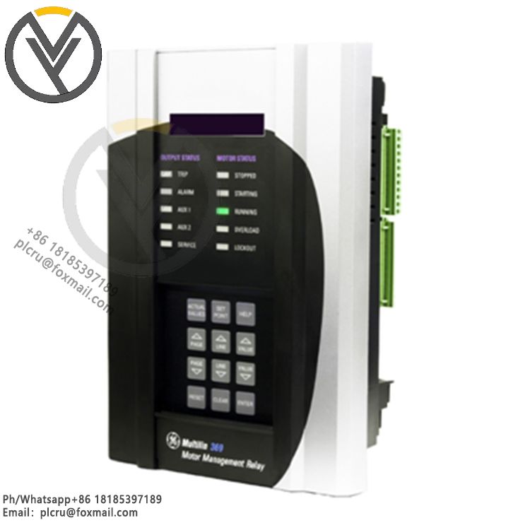
E: Equipped with Modbus TCP Ethernet communication module;
O: No harsh environment three-proof coating configuration;
E: Enhanced fault diagnosis firmware + enhanced LCD operation panel, with waveform recording and full event timing recording functions.
II. Hardware Electrical Specifications
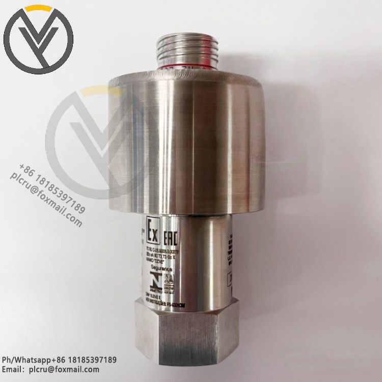
Inductor Sampling: Phase current CT secondary 1A/5A universal, grounding zero-sequence current compatible with dedicated zero-sequence CT sampling, sampling method true RMS conversion, sampling period 1.04ms, applicable to 20~100Hz power frequency;
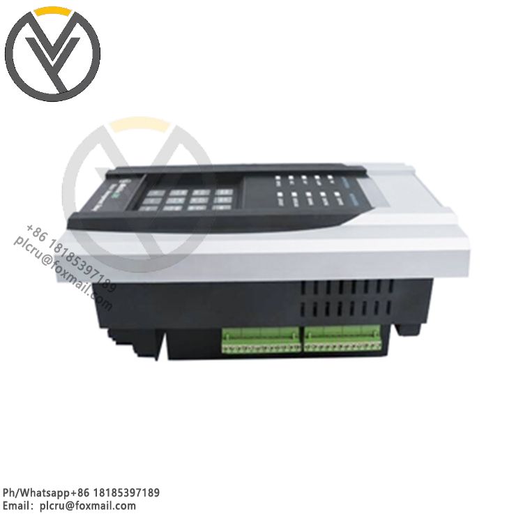
Switching Configuration: 6-channel opto-isolated programmable switch input, 4 sets of C-type normally open and normally closed programmable relay outputs, contact withstand voltage 250VAC, rated breaking capacity 10A resistive load; standard configuration includes 1-channel isolated 0~20mA analog transmitter output, selectable for current or temperature transmission to DCS;
Environment and Structure: Panel-mounted embedded installation, total weight approximately 4.5kg, operating temperature -40℃~+70℃, storage temperature -40℃~+85℃, ambient humidity ≤95% non-condensing, standard altitude below 2000m;
Communication Configuration: Standard RS485 Modbus-RTU, plus onboard Modbus TCP Dual Ethernet communication allows simultaneous access to local PLC and plant SCADA systems.
III. Full Range of Protection Functions
1. Electrical Protection: Motor inverse-time/definite-time overload stall protection, short-circuit instantaneous trip, ground fault protection, phase loss/phase imbalance, undervoltage/overvoltage, start-up timeout, reverse power, reverse rotation (back-rotation) monitoring, low current no-load protection, frequent start-stop interlocking.
2. Temperature Protection: 12 independent RTD over-temperature trip/alarm, RTD disconnection, RTD short-circuit fault alarm, segmented temperature warning logic, capable of distinguishing between bearing high temperature and winding overheat settings.
3. Auxiliary Control Functions: Motor soft start coordination, undervoltage self-start logic, fault trip counting statistics, start-stop timing control, motor starting current adaptive learning, automatically correcting the thermal accumulation curve to adapt to motor heat dissipation characteristics.
IV. Data Recording Function
The enhanced E firmware includes built-in fault waveform recording (capturing waveforms before and after a fault), millisecond-level time-stamped event logs, fault trip parameter retention, and historical power storage. Data can be viewed locally via the panel or retrieved remotely via communication, facilitating motor fault tracing and analysis.
V. Typical Application Scenarios
Suitable for complete protection systems of high-power critical motors in power plant auxiliary equipment (induced draft fans, forced draft fans, coal mills, water pumps), chemical compressors, coal mine belt conveyors, large water treatment pump sets, steel plant fans, etc.