
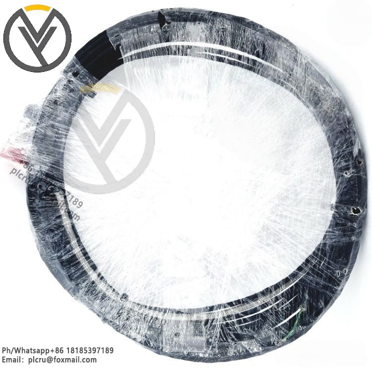
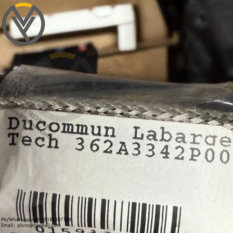
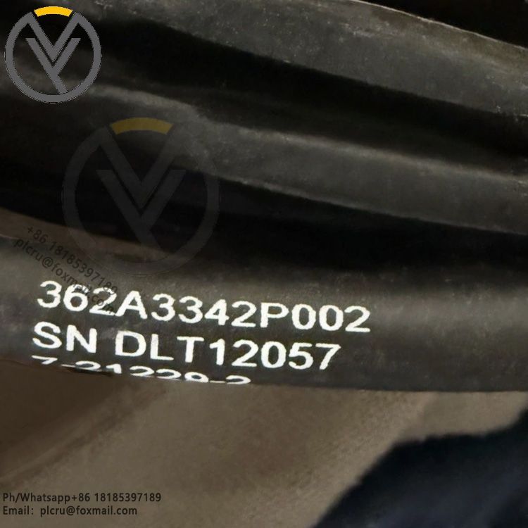
GE 362A3342P002 Flame Detector Cable 7-21229-2
Delivery time 3 days
Product origin New/used
Email plcru@foxmail.com
Mobile/wechat /WhatsApp +86 18185397189
GE 362A3342P002 Flame Detector Cable (7-21229-2)1. Basic Product IdentificationM
GE 362A3342P002 Flame Detector Cable 7-21229-2
GE 362A3342P002 Flame Detector Cable (7-21229-2)
1. Basic Product Identification
Main OEM part number: 362A3342P002Internal drawing reference code: 7-21229-2Brand: GE Vernova / General Electric Gas Turbine DivisionProduct type: CableSIC 2-wire silicon insulated flame scanner signal cable, factory pre-terminated molded assemblyLegacy replacement model: Direct substitute for old part 362A1053P104System compatibility: GE Frame 6F, 7F, 9F heavy-duty gas turbines, matched with Mark V, Mark VI, Mark VIe turbine control systemsMatching sensor: Dry type SIC silicon flame detector / Fireye high-temperature flame scannerOverall assembly weight: Approximately 8 kg for complete factory cable assembly
2. Cable Core & Internal Construction
Conductor layout: Dual independent signal cores (2-wire dedicated flame sensing circuit)Conductor material: Tinned stranded oxygen-free copper, optimized for low impedance flame signal transmissionCore insulation material: High-temperature silicon rubber composite, core insulation rated for continuous high ambient heat near combustor sectionsShielding structure: Full wrapped aluminum foil shielding plus tinned copper braided overall shield, complete EMI/RFI suppression against turbine high-voltage ignition noise, variable frequency drive interference and power plant harmonic distortionInner separating layer: Polyester buffer tape to prevent shield abrasion during vibration and thermal expansion cyclesOuter protective jacket: Oil-resistant, flame-retardant chloroprene rubber outer sheath, resistant to turbine lube oil, fuel gas mist and coolant fluid splashesAnti-kink reinforcement: Molded strain relief boot integrated at both cable ends to eliminate conductor breakage under engine room continuous vibration
3. Length & Termination Hardware
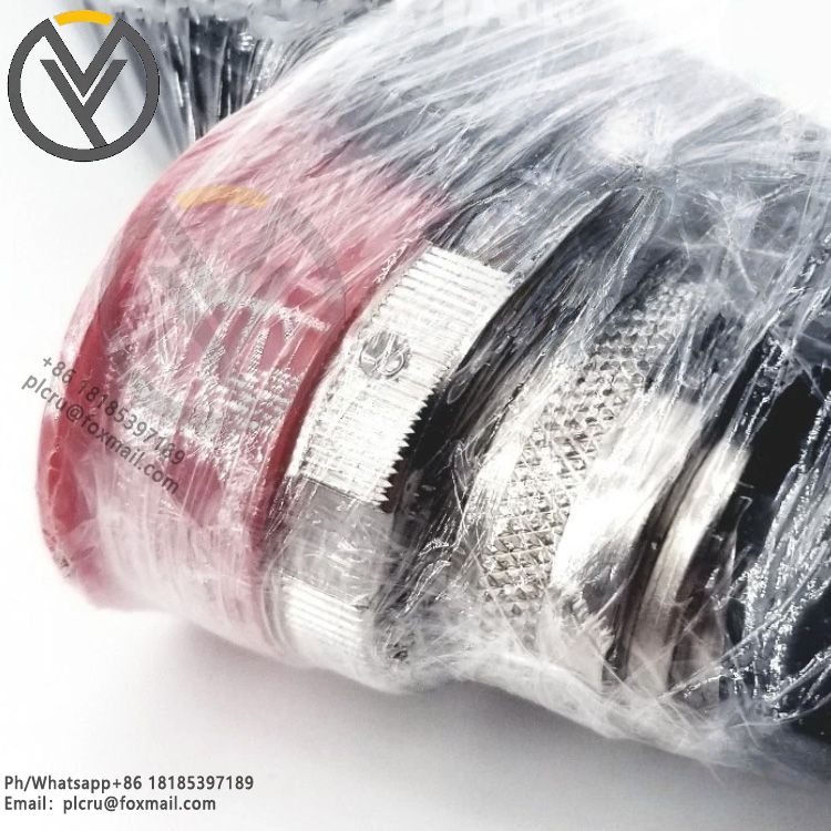
Standard factory fixed length: 18.1 meters (60 feet) pre-assembled cable lengthEnd connector specification: Both ends factory overmolded sealed MIL-spec circular metal connectors with stainless steel housingSensor-side connector: 90-degree elbow right-angle molded plug for compact mounting on combustor flame scanner probe, built-in spring lock anti-vibration latching mechanismControl cabinet-side connector: Straight male circular plug for direct mating to flame signal terminal junction box inside turbine control cubicleSealing performance: All connector mold joints fully waterproof and dustproof, rated for exposure to humid engine compartment atmosphere without ingress
4. Electrical Performance Parameters
Rated operating voltage: 300 V signal control ratingDielectric withstand test voltage: 2000 V AC between core to shield, 4000 V AC core-to-core factory acceptance testConductor DC resistance: Low-resistance design to preserve weak flame photocell analog signal without attenuation over full 18.1m lengthInsulation resistance: Minimum 1000 MΩ·km at 20°C ambient temperatureSignal transmission characteristic: Optimized for low-level DC photocurrent flame sensor signals, avoids signal distortion that triggers false flame-out or false flame detection alarmsGround loop suppression: Continuous 360-degree shielding reduces common-mode noise between turbine hot section and grounded control room cabinet
5. Thermal & Environmental Operating Ratings
Continuous operating temperature range: -50°C up to +180°C near combustor routing areasShort-term peak transient temperature tolerance: Up to 220°C for brief heat soak conditionsStorage and transportation temperature range: -60°C to +85°CHumidity tolerance: 5% to 98% non-condensing relative humidity, suitable for coastal power plant and combined-cycle turbine enclosuresChemical resistance: Resistant to natural gas, diesel fuel, turbine mineral lube oil, glycol coolant, dilute alkaline and acidic cleaning solutionsFlammability compliance: Self-extinguishing outer jacket conforming to UL flame retardant standards, no dripping molten plastic under fire exposure
6. Mechanical Installation Specifications
Minimum static fixed installation bending radius: 8 times overall cable outer diameterMinimum dynamic flex bending radius (engine vibration displacement): 15 times cable outer diameterVibration endurance: Passes GE turbine standard long-cycle vibration testing at 0.8g across 10–2000 Hz frequency band, no internal wire fatigue failureImpact resistance: Connector molded boots absorb mechanical impact during maintenance and cabinet routing workMounting compatibility: Designed for cable tray, flexible stainless steel metal conduit and bulkhead gland routing inside gas turbine enclosure, no special protective tubing mandatory for standard frame installation
7. System Functional Matching Logic
Signal function: Transmits low-amplitude analog flame intensity signal from combustor-mounted SIC silicon flame scanner back to Mark series turbine flame amplifier cardSafety impact: Damaged or degraded shielding on this cable causes noisy flame signals, leading to unplanned turbine trips, lockout startup interlocks or nuisance flame fault alarmsSystem wiring rule: Each individual flame detector requires one dedicated 362A3342P002 cable assembly; multi-drop parallel wiring is not permitted per GE control system design specificationsGrounding requirement: Cable shield single-point grounding only at control cabinet junction box end; hot turbine scanner end shield left floating to eliminate thermal ground loop currents
8. Compliance & Industry Certifications
Power plant safety certification: UL AWM industrial control cable listingElectromagnetic compatibility: CE EMC compliance for power generation heavy machinery environmentsTurbine OEM qualification: Full GE Frame gas turbine factory type qualification test passedHazardous area compatibility: Suitable for Class I Division 2 gas turbine machinery enclosures with proper metal conduit routingRoHS environmental compliance for restricted hazardous substance limitsLong-term reliability MTBF rating: Over 150,000 continuous operating hours under typical combined-cycle power plant duty cycle
9. Typical Application Scenarios
GE Frame 6F, 7FA, 7FB, 9FA heavy-duty gas turbine combustor flame detection signal wiringCombined cycle power plant gas turbine monitoring and protection systemCogeneration CHP turbine units equipped with dry SIC silicon flame scannersIndustrial simple-cycle power generation gas turbines with Mark V / Mark VIe control cabinetsOffshore platform gas turbine generator flame monitoring interconnection
10. Maintenance & Replacement Notes
Full pre-terminated assembly design, field splices or mid-length cable repair are not approved by GE OEM specificationsReplacement requirement: When outer jacket cracking, connector seal degradation or internal wire breakage is detected, complete cable assembly must be swapped rather than partial repairMatching spare accessories: Stainless steel protective flexible metal conduit, bulkhead cable glands, junction box terminal blocks and flame amplifier signal cardsFactory packaging: New units supplied sealed in anti-static moisture barrier packaging with full GE part traceability documentation and 12-month original equipment warranty
Product Tag: