
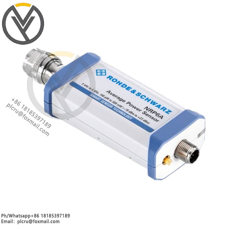
Rohde & Schwarz NRP6A EMC Average Power Sensor
Delivery time 3 days
Product origin New/used
Email plcru@foxmail.com
Mobile/wechat /WhatsApp +86 18185397189
I. Basic Model and PositioningOriginal part number 1424.6796.02, belonging to th
I. Basic Model and Positioning
Original part number 1424.6796.02, belonging to the NRPxxA three-channel diode-type average power probe, specifically developed for EMC electromagnetic compatibility testing scenarios. It accurately measures only RF average power, with minimal measurement error for amplitude modulation, frequency modulation, pulse, and other modulated signals.
II. Core Specifications for Frequency and Power Measurement
Operating Frequency Range: 8kHz to 6GHz, covering power frequency harmonics, wireless communication, and general EMC radiated/conducted testing frequency bands. The lower frequency limit covers interference measurements from switching power supplies and inverters.
Linear Power Range: 100pW (-70dBm) to 200mW (+23dBm), with a dynamic range of 93dB throughout. Stable measurement of continuous wave and various modulated signals is possible.
Ultimate Withstand Power: Long-term average withstand power of 1W; short-term peak envelope power of 2W; pulse width limit of 10μs. Exceeding these limits may damage the diode detection path.
Harmonic Suppression Characteristics: The probe features a built-in filter structure, exhibiting low sensitivity to second and third harmonics. Clutter interference is minimal during EMC amplifier output and interference source power measurement.
III. Impedance Matching VSWR Parameters: VSWR is less than 1.25 in the 8kHz to 20kHz band; less than 1.13 in the 20kHz to 2.4GHz band; and less than 1.18 in the 2.4GHz to 6GHz band. Excellent impedance matching performance across the entire frequency band reduces measurement deviations caused by signal reflection. The RF input interface is a standard N-type male connector.
IV. Measurement Architecture and Accuracy Characteristics: Utilizing a three-channel diode detection architecture, unlike single-diode probes, it significantly reduces reading drift caused by signal modulation. Built-in original factory calibration data storage automatically retrieves compensation parameters upon power-on, supporting internal self-calibration functions, allowing for status verification without an external standard source.
Fast measurement response speed, suitable for continuous acquisition and long-term steady-state power monitoring, meeting the needs of long-term frequency sweeps and fixed-point irradiation power monitoring in EMC testing.
V. Interfaces and Connection Methods
Digital Communication Interface: A dedicated six-pin interface at the probe tail, offering two connection options; with an NRP-ZKU USB direct-connect cable, it can be directly connected to a computer for independent use running the NRPV virtual power meter software; with an NRP-ZK6 cable, it connects to the NRX power unit, allowing up to four NRP series probes to be connected simultaneously to one NRX unit.
Compatible Equipment: Compatible with all R&S signal generators, spectrum analyzers, EMI test receivers, power meter units, and other similar platform test instruments; supports remote control and power value reading via programmable SCPI commands.
VI. Mechanical, Environmental, and Physical Specifications
Weight: 0.18kg; Metal shielded casing; resistant to external RF interference; suitable for use in complex electromagnetic environments such as EMC anechoic chambers and shielded rooms.
Operating Temperature: 0℃ to 50℃; Storage Temperature: -20℃ to 70℃; Stable operation under non-condensing conditions with a maximum humidity of 95%.
Mechanical Protection: The casing is wear-resistant and impact-resistant; the N-connector has a standard tightening torque; it is durable for frequent plugging and unplugging calibrations and for use with attenuators.
VII. Typical Application Scenarios
Monitoring of average power amplifier output power in EMC radiated and conducted emission testing; Calibration and stability verification of RF power amplifier and signal source output power; Average transmit power detection of wireless devices and industrial RF modules; Measurement of low-frequency switching interference and power supply harmonic RF components; Laboratory benchmark comparison and production line batch power sampling calibration.
VIII. Important Notes for Use
Do not exceed the short-term peak power limit of 2W/10μs and the long-term average power limit of 1W. An attenuator must be used in high-power applications.
The cable must be the original manufacturer's NRP-ZKU or NRP-ZK6 dedicated cable. Third-party alternative cables may cause communication loss and abnormal calibration parameter readings.
This device only measures average power; it lacks the ability to accurately measure peak power and pulse envelope. For high-precision pulse peak measurements, the NRPxxS pulse-specific probe must be used.
A complete calibration certificate is included with the product. It is recommended to have it recalibrated annually by a metrology institution to ensure EMC testing compliance accuracy.